Prelab
I2C Address
The ToF sensors show an I2C address of 0x29. The spec sheet often lists 0x52, but that value includes the read/write bit. In practice, the useful 7-bit address is 0x29, and 0x52 is the 8-bit form that is effectively shifted due to the R/W bit.
Approach to Using 2 ToF Sensors
I will cycle the two sensors on and off, collecting measurements during the on periods in order to address the sensors separately. To do this, I will create a loop that toggles a shutdown pin so only one sensor is active at a time during address configuration, then I will assign a new I2C address and re-enable the second sensor so both can be read without conflicts.
Placement of Sensors and Missed Obstacles
I will use one sensor on the front and one sensor on the side of my robot. This allows forward distance measurement and lateral distance-to-wall measurement during turns. Obstacles can be missed if they are outside the ToF field of view, too low/high relative to the sensor mounting height, very thin, angled to reflect poorly, or temporarily blocked by the chassis during turns.
Wiring Diagram Sketch
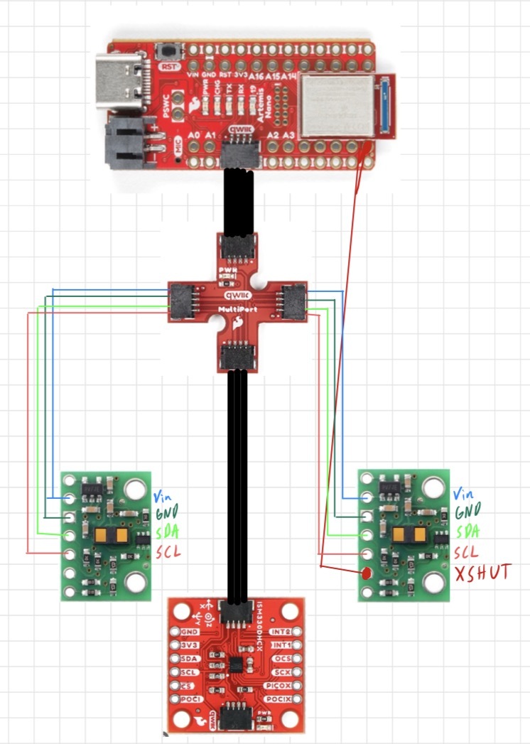
Lab Tasks
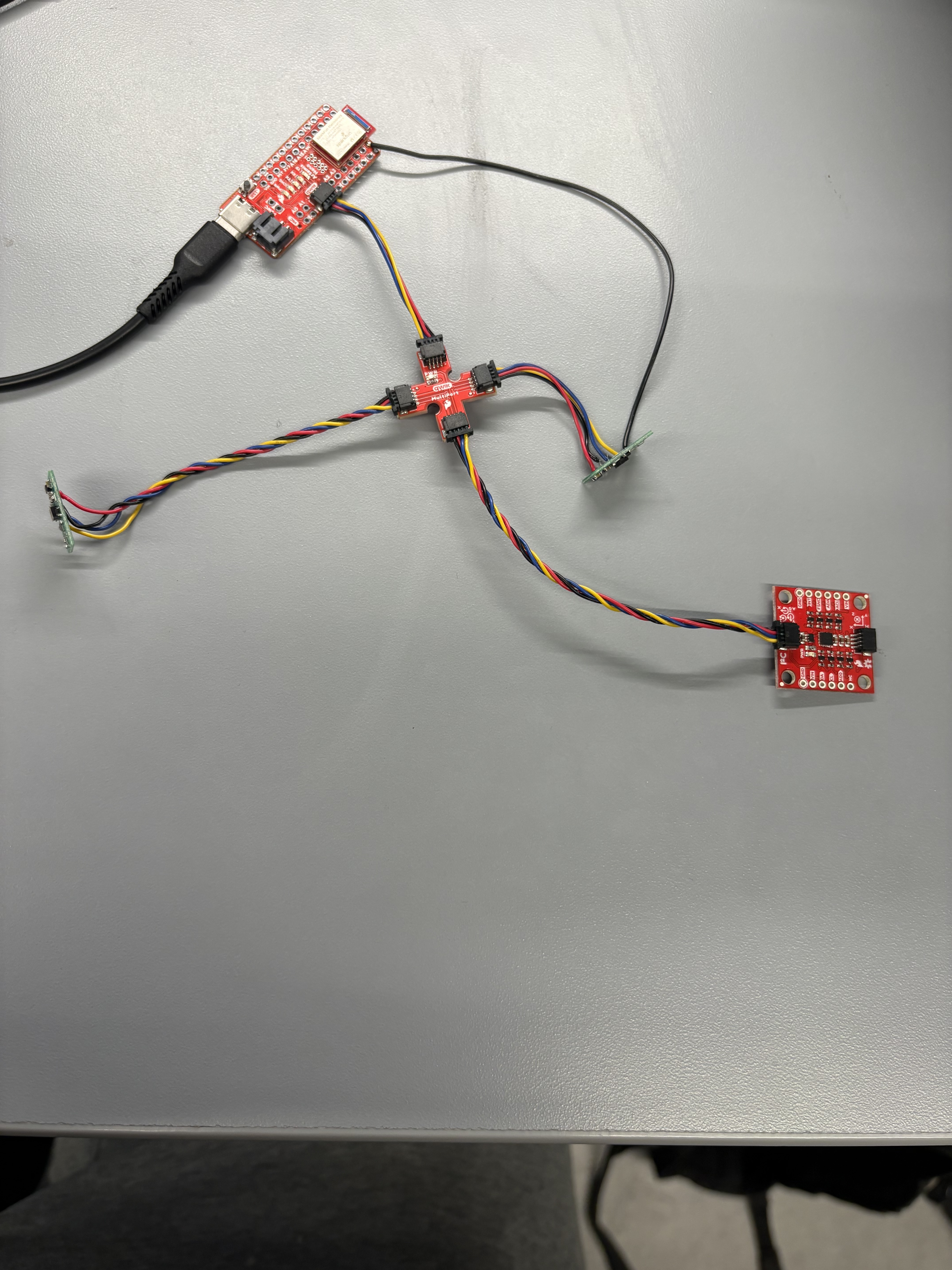
ToF Sensor Connected to QWIIC Breakout Board
Below is a picture of the ToF sensor connected to the QWIIC breakout board on my Artemis.
Artemis Scanning for I2C Devices
The scan reported 0x29 for the ToF sensor, consistent with the 7-bit I2C address format used by the microcontroller.
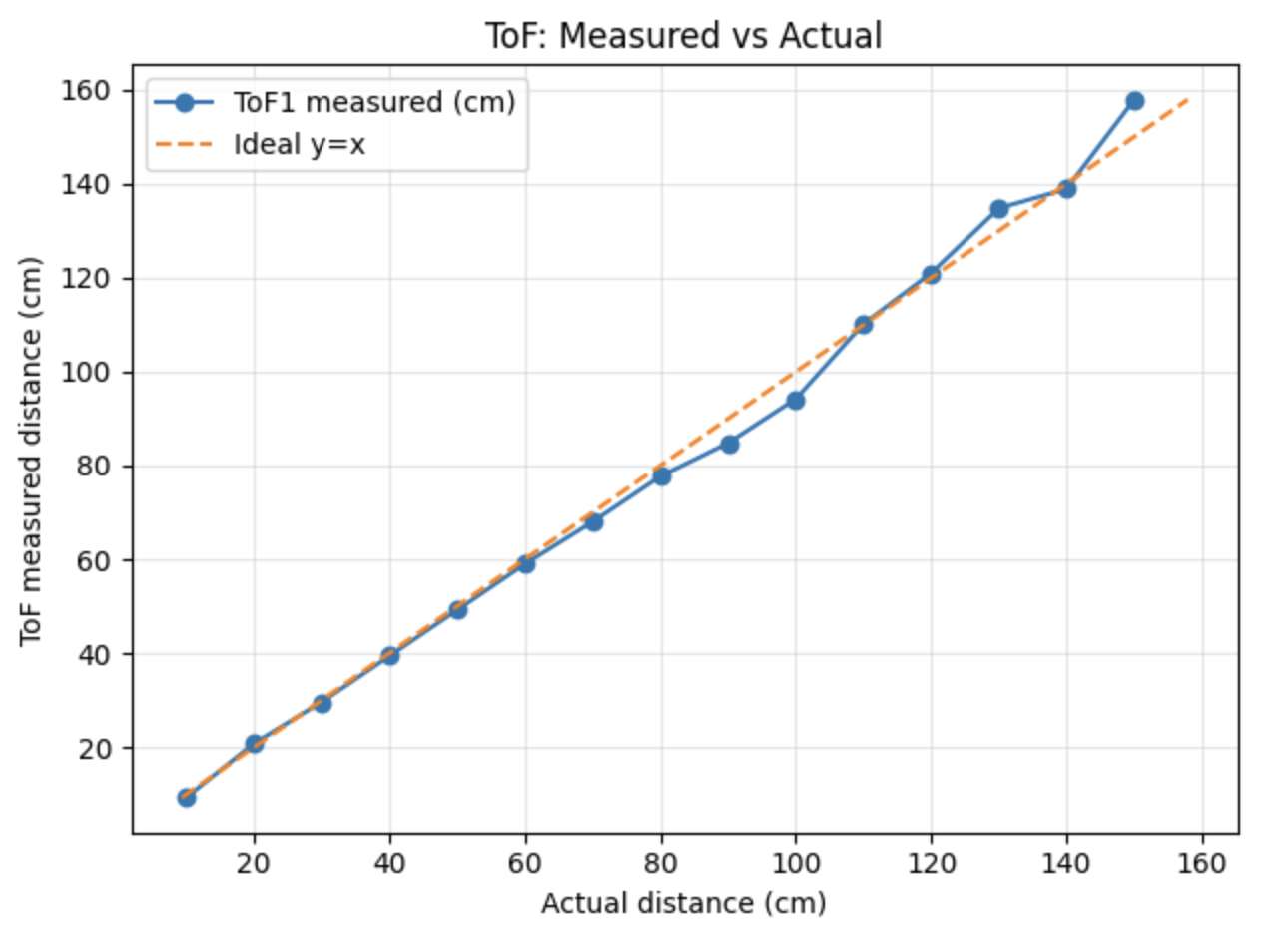
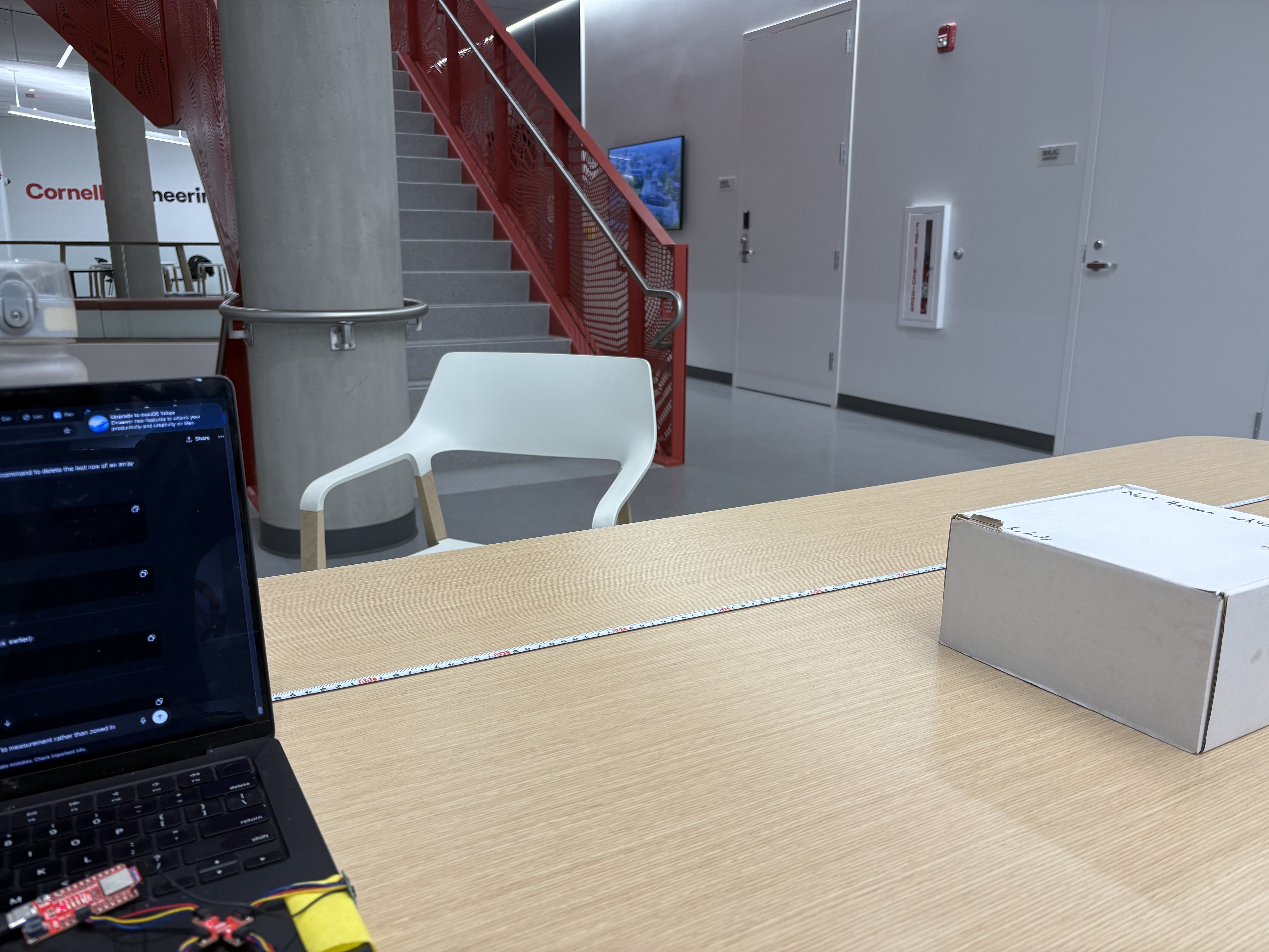
Sensor Data in Chosen Mode
I am going with long-range mode in order to be able to best map a room. I sampled up to about 1.5 meters to test accuracy using a tape measure.
ToF Sensor Speed
In future labs, it is essential that the code executes quickly, therefore the program cannot hang while it waits for the sensor to finish a measurement. I implemented a non-blocking loop that prints the Artemis clock continuously and only prints new ToF data when it is ready. The loop timing is useful for estimating how fast the firmware can iterate when it does not block on sensor reads.
Non-Blocking ToF Logging Code
case COLLECT_TOF_CONT: {

  Serial.println("Starting non-blocking ToF collection (25 loops, ms)...");

  tof1.startRanging();
  tof2.startRanging();

  int last_loop_ms = millis();

  for (int i = 0; i < 25; i++) {

    int now_ms = millis();
    int loop_dt_ms = now_ms - last_loop_ms;
    last_loop_ms = now_ms;

    Serial.print("Time(ms): ");
    Serial.print(now_ms);
    Serial.print("   Loop_dt(ms): ");
    Serial.print(loop_dt_ms);

    tx_estring_value.clear();
    tx_estring_value.append("TOFNB:");
    tx_estring_value.append(now_ms);
    tx_estring_value.append(",");
    tx_estring_value.append(loop_dt_ms);

    if (tof1.checkForDataReady()) {
      int distance1 = tof1.getDistance();
      tof1.clearInterrupt();

      Serial.print("   TOF1(mm): ");
      Serial.print(distance1);

      tx_estring_value.append(",D1:");
      tx_estring_value.append(distance1);
    }

    if (tof2.checkForDataReady()) {
      int distance2 = tof2.getDistance();
      tof2.clearInterrupt();

      Serial.print("   TOF2(mm): ");
      Serial.print(distance2);

      tx_estring_value.append(",D2:");
      tx_estring_value.append(distance2);
    }

    Serial.println();
    tx_characteristic_string.writeValue(tx_estring_value.c_str());

    delay(5);
  }

  tof1.stopRanging();
  tof2.stopRanging();

  Serial.println("Finished 25-loop ToF collection.");
  break;
}
The output includes a loop timing value that represents the time in milliseconds between loop iterations. TOFNB stands for ToF non-blocked. The intentional delay and the time required for Serial printing and BLE notifications can reduce the maximum loop frequency.
Speed and Limiting Factor
The loop executes quickly when it is not blocked by waiting for a measurement. The current limiting factor is the sensor update rate, plus overhead from Serial printing, BLE notification bandwidth, and the intentional delays added to keep the data stream stable. Below is the data output from an analysis of the initial TOF_COLLECT loop I wrote, which only sent data when the TOF sensors were ready.

2 ToF Sensors and the IMU
I updated my firmware to read both ToF sensors and the IMU in parallel. For ToF, data is recorded when available, and when a measurement is not ready the system outputs NA for that sensor. For the IMU, I recorded roll and pitch using the complementary filter to get an estimate that is both stable and responsive.
I used the continuous record approach and adjusted my IMU loop to send over an array of data for a period defined in the send_command statement. I call the new case GET_INFO. In this case it records IMU data as fast as possible, records ToF data when available, and outputs NA for either sensor when the data is not available. I recorded for 7 seconds, moved the box away, and rolled the IMU sensor to create clear changes in roll and pitch.
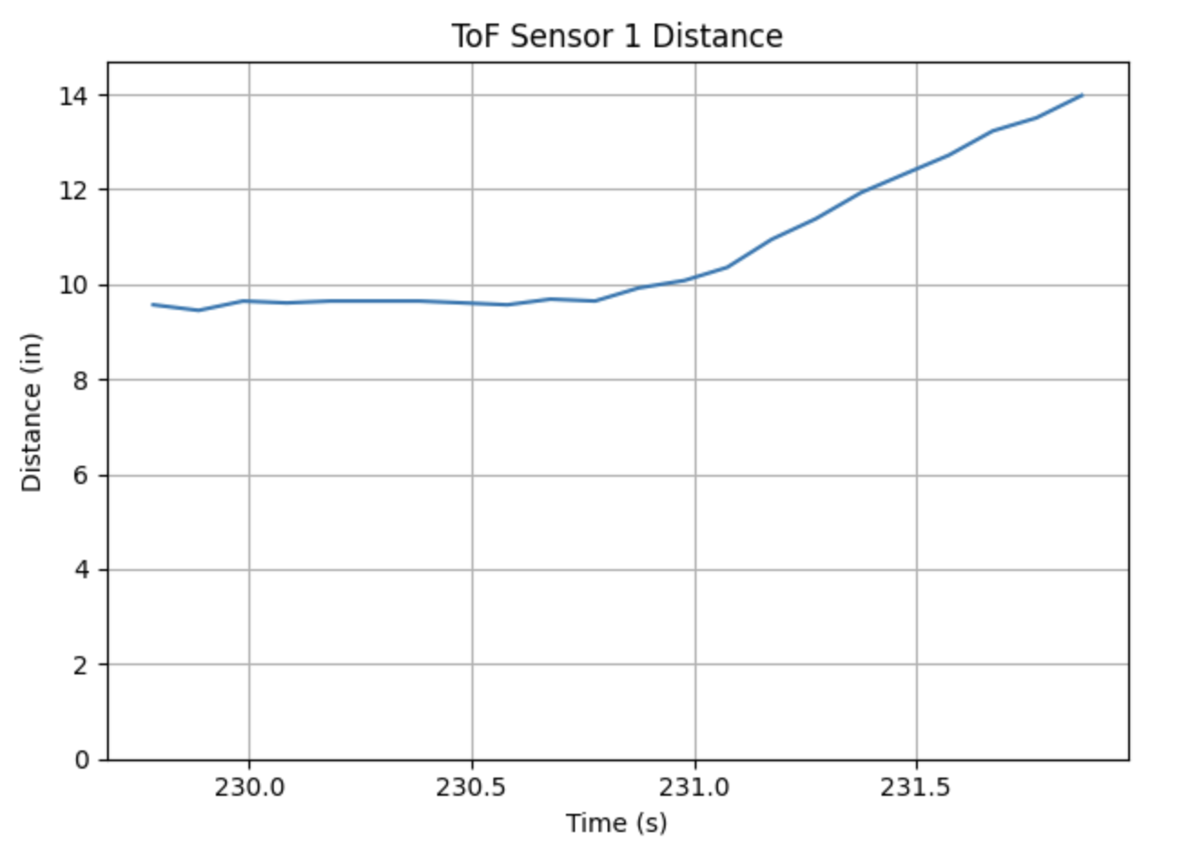
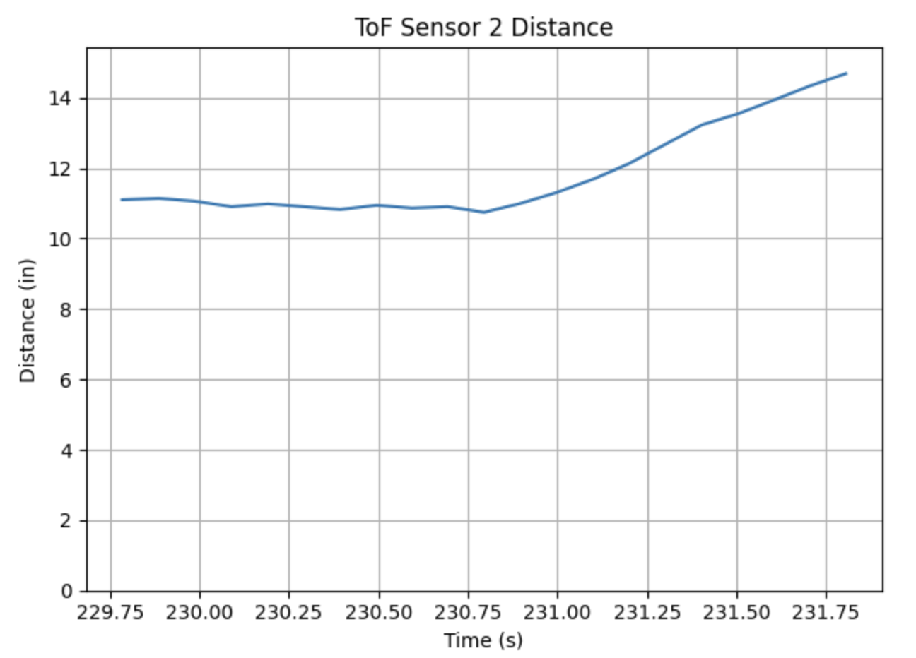
Time v Distance
I used my continuous record routine and logged distance readings from both ToF sensors over Bluetooth. When a measurement was not ready, that sensor output NA. The plots below show distance vs time for both sensors using data sent over BLE and parsed into arrays in Python.
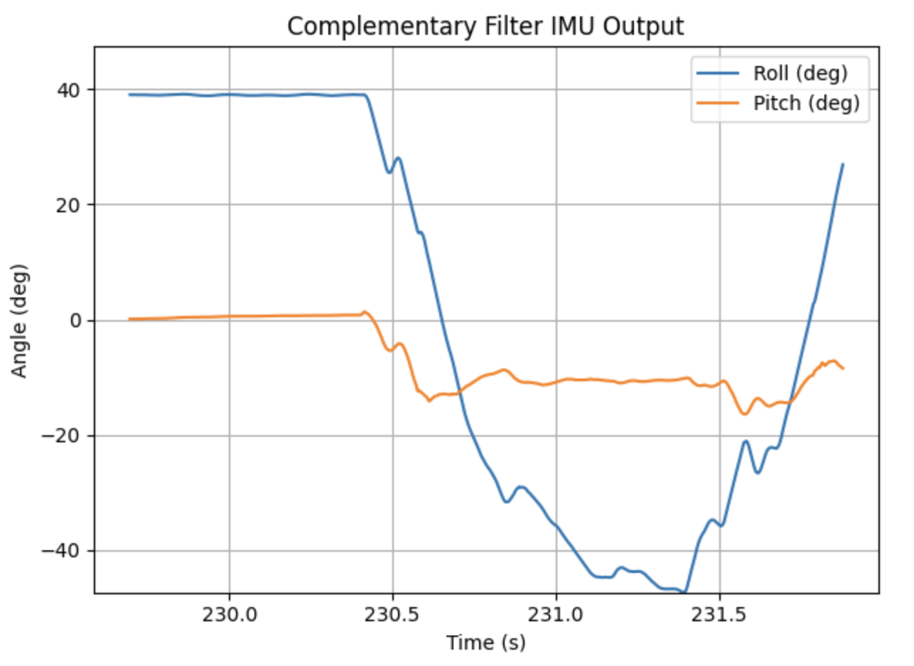
Time v Angle
I adjusted my IMU loop to send over an array of data for a period defined in the send_command statement, implemented as the GET_INFO case. The plot below shows roll and pitch over time from the complementary filter output created from the Bluetooth dataset.
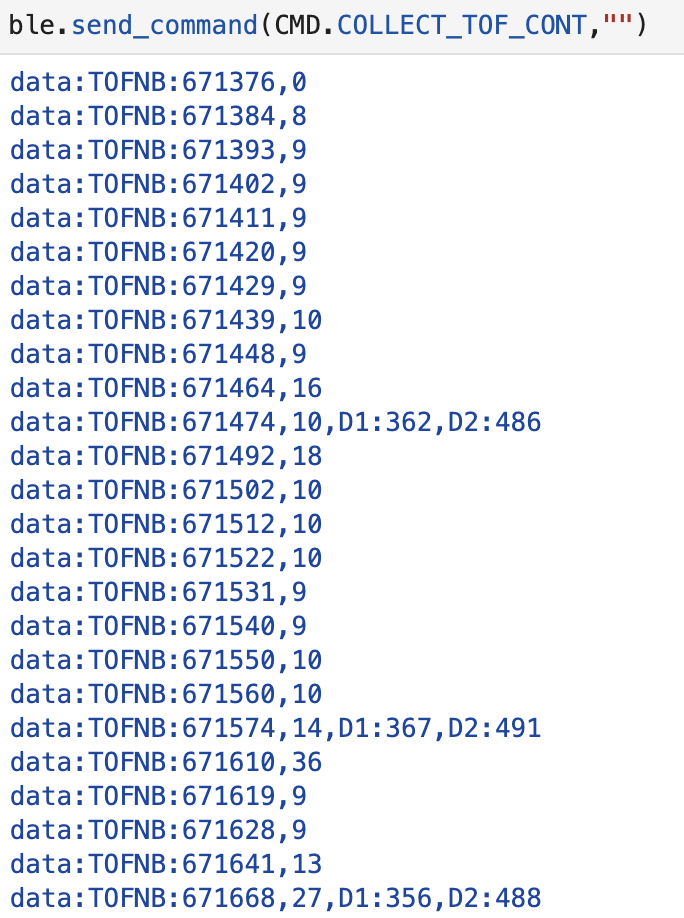
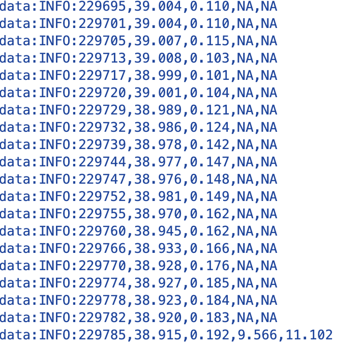
Parallel Data Capture
The image below shows the raw Bluetooth output used to generate the plots above, demonstrating that ToF and IMU values were streamed together.
References
For this lab, I worked with Coby Lai when I ran into coding issues. I referenced Aidan Derocher's student page when I was stuck as well. I also used ChatGPT for help with syntax, coding, and page structure.